| A Tinkerer's Guide to 35, part 2 |
|
Repairing an Atwater Kent Model 35
© 2008, Richard Fairbanks
|
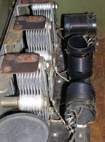 |
| RF section with 3 tuned circuits |
|
|
One of the first things to do is to vacuum out spider webs, little piles of dirt and grass, evil spirits, and rat droppings. Grass? Yes. Like white on rice, grass was firmly stuck to the three RF transformers (those short toilet-roll sized things). A protective lacquer coating on those transformers had probably softened in the summer heat and petrified the grass.
Two of the three RF transformers were seriously damaged. They have dozens of turns of wire wrapped in a single layer along a tubular form, with another series of wraps at one end on top of the first layer. A classic "open air" design.
|
One of my damaged transformers, RFT-3, had a few loose wire stubs sticking out of both ends, which as you might guess was not a good sign. There was no continuity in either winding. Its primary winding, the short layer on top, was obviously damaged in several places.
|
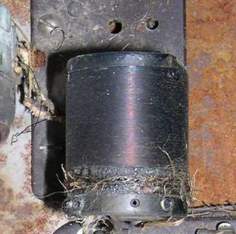 |
| Damaged primary of RFT-3 |
|
|
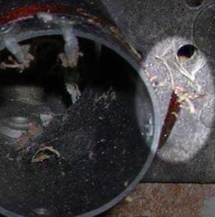 |
| RFT-2 severed primary |
|
| RFT-2 was not much healthier. Its primary had been severed and pulled away from the rest of the assembly. Those evil spirits had been busy! The primary coils on both RFT-2 and RFT-3 would have to be replaced. So, I set them aside to look for an easier task!
|
I decided to remove the chassis from its rusty breadbox grave, an easy task! A few drops of Liquid Wrench helped loosen the screws. The chassis had a few patches of rust and was in need of a thorough scrubbing, but otherwise it was good. Out of six tubes needed, four were present. I called upon a trusted Canadian helper to test the old relics, my trusty Stark tube tester. A quick check of each tube showed…well, not much. One was weak, two barely moved the meter, and a fourth was totally DOA. (I was subsequently able to revive two of them with a last-ditch technique called "rejuvenation".)
|
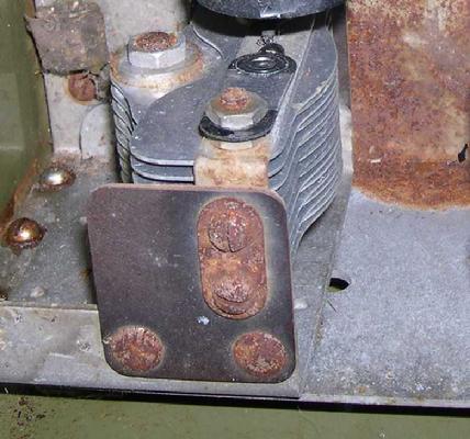 |
| One of three tuning capacitors |
|
| All three tuning capacitors had rust on their bottoms yet the mechanical linkage between their rotating shafts was in perfect condition. After a good cleaning and some fresh grease on the bearings everything turned smoothly. "Grease is the word."
|
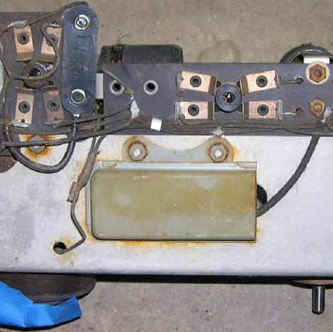
I checked the small number of resistors and capacitors and found a couple of problems. There is a .3uf capacitor held inside a metal box bolted to the chassis. This “plate bypass” capacitor keeps B battery power (67v) for the RF tubes noise free. It showed some current leakage which interfered with my DVMM’s ability to read its actual capacitance value. Leakage is a very common trait as the materials in these old parts degrade and moisture seeps in. I figured a little leakage would not hurt anything, considering its circuit position, so I postponed replacement. If it did not cause any problems once the radio was working, I’d leave it alone. next
|
 |
| Plate bypass capacitor |
|
|
|
|