| A Tinkerer's Guide to 35, part 3 |
|
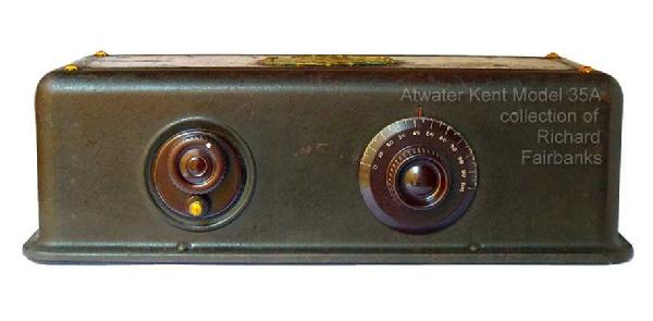
Repairing an Atwater Kent Model 35
© 2008, Richard Fairbanks
|
The left knob serves as a volume control, turning a rheostat that adjusts filament voltage to the three RF tubes. (Lower voltage means cooler filaments, reduced amplification, thus lower volume.) It measured okay but turned like a pepper grinder. Not good. I wanted to open it for cleaning but ran into trouble. I needed to remove it from the chassis but there was not enough slack in its connecting wires. Of the three wires, one is not an ordinary wire at all. It is really a 7 inch piece of special wire that forms a 1 ohm resistor. Resistance wire like this must not be broken, cut, or damaged in any way because the wire's length determines its value and any damage can only be repaired by shortening it. It could not be disconnected because the connection is inside the rheostat, which I could not yet open. A "Catch 22". Drat those evil spirits! I would have to disconnect the far end of the wire and pull it free, very carefully. The resistance wire is threaded through a couple holes in the chassis and it is covered by an insulating tube that has become stiff with age, rigor mortised if you will, retaining the shape of its path and making extraction difficult. I know from experience the resistance wire itself can be broken easily doing this, and I would certainly have trouble with the stiff insulator. There seemed little other choice, though. There were a few crunching sounds as I worked it free and I noted some stress marks in the insulator at one of the sharp bends, but the brittle stuff was intact. I was lucky.
|
 |
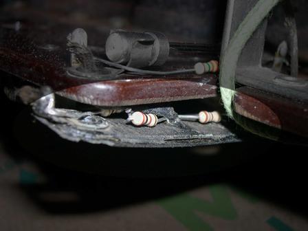
| Bottom view of grid bias resistor |
|
| Just under the detector tube socket is a "grid bias" resistor, a flat 450 ohm wirewound with a center tap at 180/270 ohms. It had no continuity at all. Some restorers might try to unwind/rewind the resistor to fix it, in order to keep things original. I once tried that approach, on a different radio, only to have the aged brittle thing break into short pieces as I unwound it. Rather than risk a similar outcome now I simply soldered a couple of standard Ľ watt carbon resistors across it! The original part remains in place, unaltered, should a future owner dare to rewind it. Meanwhile my new parts are mounted on its top side and will not be visible when the chassis is installed.
I have to say that replacing an old wirewound part with a modern carbon resistor is not the right way to do it! Nothing will be harmed but carbon resistors do not have any inductance, which a wirewound has. The radio might be more susceptible to squealing or instability with my cheap substitute.
|
 |
| Closeup of grid bias resistor after repair |
|
|
Another bad resistor was found nearby, a 2 megohm “grid leak” resistor. Grid leak resistors provide higher resistance values than wirewound resistors of the day could provide. In fact, a whole niche market grew up around grid leak resistors. Ad departments bragged about these marvelous little high-tech devices that somehow caused magical “detection” to happen, whatever that was. Actually, all magic was performed by the detector tube. The resistor is just a dumb helper. It is just a strip of paper-like material impregnated with carbon or graphite, held inside a small tube. Those sharp ad men knew how to exploit an angle! Radio owners could buy several sizes and values in colorful glass. For a little extra cash they could buy special adjustable designs for customized tweaking.
Those of us who work on old equipment know that these resistors, like all carbon-based resistors, increase in value as they age. This one measured 8 megohms, not 2. Some increase is usually tolerable but a 4 fold increase is probably too much. I soldered a small 3.3M resistor in parallel with the glass part, for a combined resistance of about 2.5 megohms. It is mounted to the side of the original, hardly noticeable, and can be removed without taking the radio apart should a suitable replacement be found in the future.
|
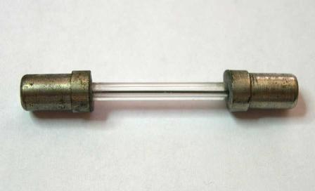 |
| Glass cases grid leak resistor |
|
|
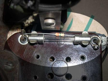 |
| Grid leak repair |
|
|
Most of the connecting wires below the chassis were in excellent condition. On the top side a few were badly frayed or missing insulation. Unfortunately, mice tend to nibble away at everything and cloth insulation is a tasty treat to a famished little mousy. I decided to replace the bare ones with new cloth covered wire. I really do not like the modern stuff. It is just regular plastic-insulated wire with a somewhat stiff cloth-like outer layer, it is NOT as classy as original cloth wire. I've been wondering if the little critters like the newer stuff. Time will tell.
When replacing wire in antique radios, wire length and layout can affect proper operation. It is important to exactly duplicate each wire's length and placement, particularly when they are in an RF circuit like these were. next
|
|
|