| A Tinkerer's Guide to 35, part 5 |
|
Repairing an Atwater Kent Model 35
© 2008, Richard Fairbanks
|
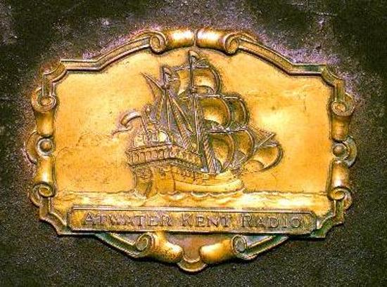 |
| Atwater Kent's logo on top of the case |
|
We're getting close to the finish line! The chassis was cleaned, parts repaired, tuning caps greased, and bare wires replaced. I reinstalled the volume rheostat, threading that brittle resistance wire back into position, ever so carefully. Next up? Tubes.
I had been able to rejuvenate two of the four 01A’s that came with the radio. Rejuvenation is a last-ditch attempt to extend a tube's useable life. It works only on some types of early tubes, does not always give results, and requires a willingness to risk a tube's destruction for the possibility of a few more years of life. According to my tester, one of the two was still rather weak. I had a few good 01A's stashed away in a sock drawer and was just able to muster a full set of 6. I hoped the weak one would work okay in circuit despite its weak showing. I placed it as the detector. Why? The set can be outfitted with different tube sets, 01A’s in all six positions is only one option. The detector stage is advertised to work with a 01A, 00A, or 112A, some variance is apparently tolerable, so it made sense to me to put the weakest tube there to start. While we’re on the subject, there is also some flexibility in choice of audio output tubes, which can be a 01A, 112A, or 71A. The latter can handle higher plate currents than a 01A. Did that mean we could crank up the volume to 11 just by putting in a different tube? I wanted to experiment with this a little more but decided to use all 01A’s until the radio was working.
This radio includes the speaker or headphone coil as part of the output tube circuit. The radio’s output tube receives power directly through it. Rather than place a valuable antique speaker in harm’s way, for now I substituted a 2000 ohm resistor and connected a small amplifier/speaker across it to listen with (using a capacitor to block the DC voltage). No matter what went wrong, a 2000 ohm resistor would limit DC current draw enough to protect the output tube. Speaking of DC, this radio requires 5 separate battery voltages from -6 up to +90. I did not want to assemble enough batteries to do that! Several years ago I purchased a handy power supply made by Antique Radios, Inc., the Arbe III, that gives enough A, B, and C voltage choices to meet the vast majority of battery powered radios. It is a wonderful value and I cannot imagine working on radios without it.
|
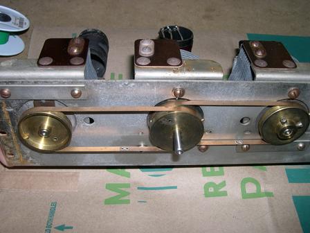 |
| Tuning linkage re-installed and adjusted |
|
Finally is was time to check and align the radio. I was concerned that the new RF transformer coils might prevent the 3 tuning sections from “tracking” together properly. A TRF radio relies on several relatively independent circuits, each of which needs to be precisely set for the station of interest. Some early radios of this design provided a separate knob for each tuned stage which meant that tuning in your evening’s entertainment could be a frustrating and time consuming experience. The idea to link multiple stages to a single knob was a major improvement, but doing so required that all stages behave the same way when the tuning knob turns. My two new coils, with their larger diameter wire, might cause the three tuning sections to behave a little differently and degrade overall performance. I am relieved that it tunes smoothly and maintains good sensitivity from end to end of the dial. Once I got the individual tuning capacitors set just right there was almost no tracking error.
Remember that .3uf “plate bypass” capacitor I mentioned earlier? Well, it turns out the cap wasn’t very good after all. I was having some real trouble with whistles as I tuned in a station. The RF section was oscillating. I swapped tubes, checked for a wiring error, and was scratching my nose when I remember the plate bypass capacitor. It was supposed to keep the plate power nice and clean. I soldered a .5uf cap from my junk box in its place and oscillations disappeared (at least until the volume knob was turned past half way). In fact, reception is slightly less noisy when the original part is disconnected. Its leakage was apparently adding noise. In an effort to improve oscillation even more I added a .22uf cap in parallel, but located near the first RF tube, oscillation dropped down a little more. That was the best I could make it so I realigned the RF section for the final time.
I swapped the weak 01A into different positions and in each it severely degraded the radio’s performance. At least it functioned as a detector, which is where I left it for the time being because I didn’t have another one. I swapped a 71A into the final output position and, still using my 2k resistor dummy load, heard no change. I put the 01A back and connected my antique Amplion “dragon fly” horn speaker instead of the 2k resistor. The sound was weak. Swapping in the 71A again, this time the audio got much louder! It sounded pretty good, actually. I reversed the speaker wires and the sound got even worse than before. A voltmeter showed me what was happening. As mentioned above, the output tube’s 90 volt plate power is supplied directly through the speaker’s coil. A 01A tube pulls relatively small plate current, under 2 milliamps. Such low current can develop only a few volts across the Amplion’s speaker coil. The 71A, with its higher current draw (16ma) was able to develop 20 volts across the Amplion. This is only DC, not actual audio signal, and shouldn’t make any audible difference. Higher DC current provided higher magnetic flux in the speaker mechanism, either boosing or counteracting its aged permanent magnet. A boost made the speaker more efficient. That’s cool but in the old days higher current would also exhaust the B battery supply sooner. Those Atwater Kent designers had given users a choice to customize their radio based on their circumstances! Not too shabby for technical heathens of the roaring twenties. By the way, a Lektophone speaker that used a different mechanism sounded the same no matter which output tube was used.
|
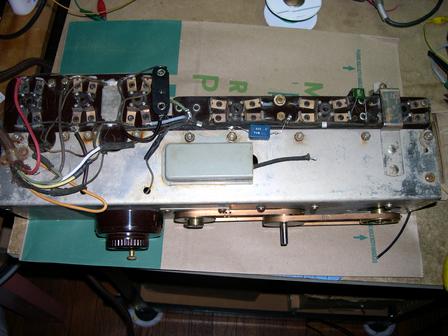 |
| Almost finished! |
|
One last task was to replace the ancient brown battery cable. Hmm, brown. They must have really liked the color brown in those days. The old cloth covered cable had multiple failures along its length. Two of the six wires were shorted together and a third had no continuity. I really hated throwing out the old wire but I wanted to have a working radio, not just a display radio, so I installed an 8 wire cloth cable available from Radio Daze, and used only 6 of the connections. It is not as flexible as I would like, but it works and it is a wonderful, soothing, and smudgy shade of brown!
-Richard Fairbanks
no reprint without permission
|
|
|