Repair of an Atwater Kent 55 Console
© 2010, Richard Fairbanks
|
 |
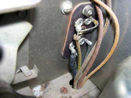
| Local/distant switch is missing a rotor wiper contact |
|
|
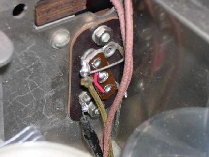
Next on the agenda is the local/distant switch. I have a knob and shaft but no rotor wiper on the back. Should I replace the switch?
I have been told that sometimes this switch was removed and a tone control potentiometer put in its place. The idea is sensible but not part of the original design so I take a pass on it. A vendor of old radio parts assures me he has a replacement swithch and quotes a price, but days later he responds to my reminder by saying he is too busy to look for it this month! I decide to make my own wiper out of a piece of terminal strip. (Sometime later I traded with another hobbiest for a proper switch but have yet to install it. This home made fix still works and I want to see just how long it will last.)
|
 |
| A section of terminal strip fashioned into a rotor wiper |
|
|
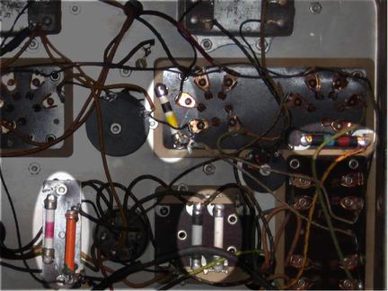
I am seeing some less-than-perfect repairs to the chassis. Few if any resistors are original parts and none display Atwater Kent’s published color coding for this radio. All but one resistors measure considerably higher than they should. Two may have been changed in an unsuccessful attempt to compensate for the partially shorted speaker field coil, as I’ll show you soon.
|
 |
| "Dogbone" resistors are wrong values |
|
|
Should I try to hunt down new old stock (NOS) resistors for the sake of keeping things “original”? Nah! NOS parts usually have aged far away from their original values. I decide to try something I’ve never done before. I read somewhere about attempts to hide modern parts inside material that is cast and painted to look similar to an original part. Since we “restuff” capacitors all the time by removing old guts and installing new parts inside their shells, is this any less acceptable? The idea appeals to me for some reason. By golly, I’ll try it with plumber’s putty epoxy!
|
|
|
From another radio I borrow a nice glass grid resistor, seen on the left, around which I will form a mold. The two resistors on the right were removed from this radio. All are very similar in size so I hope the idea will work. By the way, end caps of the two removed parts are melted where they were soldered directly onto the radio.
|
|
|
I buy a tube of Propoxy20. This stuff has a working time of several minutes before it cures into a non-conductive and practically indestructible chunk. The label says it is “steel reinforced” but in fact it is not at all conductive. To make a mold of my master part I spray the part with silicon oil and then mold putty around it. The oil prevents putty from sticking to my valuable part. I make a top half first, and after it cures I lay the master part in it and form a bottom half.
After curing, the two halves fit tightly together. My fingers roll some fresh putty around a modern metal film resistor and place the blob inside the mold (the mold halves are sprayed with silicon to prevent sticking). I quickly squish out the excess.
After a partial cure but while the putty is still pliable, my new fake part is removed, trimmed, and sanded. A paint job makes it pretty enough that I decide to make a couple more.
|
|
|
|
|
Three of these resistors are fakes, two are real. I am only moderately happy with the results. They are under the chassis and will not be seen again, which makes me wonder if it is worth all the effort. I think with practice my results can be much better, especially if metal end caps are installed, but since these parts will be invisible I’ll just solder the wires into place and use silver paint for the end caps. Whether or not I go to this extent again, it was an interesting exercise.
next-->
|
|
|
|