Repair of an Atwater Kent 55 Console
© 2010, Richard Fairbanks
|
Am I finally ready to plug it in and let it sing? Tubes in! Switch on! Crackles from the speaker! Voltages checked! RF alignments made! A old champ sings again!
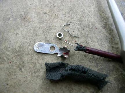
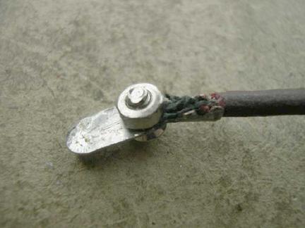
There is another problem, though. The pilot lamp is intermittent. There is a 2 ohm length of resistance wire in a sleeve that runs up through the chassis to a bulb socket over the tuning indicator. The wire broke about ½ inch below the socket and the slightest movement jiggles the broken ends.
|
I cannot just solder the break together. Any of you who have tried to solder nichrome wire knows that solder molecules and nichrome molecules are not friendly neighbors. They do not bond. A crimped connection is best. The wire had been riveted to a small metal lug which was in turn soldered to the lamp socket. I remove the rivet and use a screw and bolt in its place. The former 2 ohm (now 1.9 ohm) resistor is half an inch shorter and there is barely, just barely, enough wire remaining to connect.
The radio is working well now but I am not done quite yet. That original power cord is an incredibly brittle hazard. Frankly, I hope I fare as well at this age but it makes weird crunchy noises as it is flexed.There is no way it is staying on the radio. Brand new cloth-covered 2 conductor cord looks just right. I prefer 2 conductor over larger and less flexible 3 conductor cord.
|
 |
| Broken section of resistance wire removed |
|
|
 |
| Resistance wire and lug, ready to install |
|
|
|
|
In the old days, they rarely put fuses on individual appliances. I want a fuse on this chassis, though. Since it is obviously not original to the radio I hope to keep it out of view. After much self debate I finally decide to mount it under the chassis with thick fish paper around it to ensure no contact with the chassis can happen. The fuse should never need replacing unless the radio needs repair, so I am comfortable with hiding it. A note alerting to its presence will be placed with the radio.
|
You may recall that I did not replace the filter capacitors. They appear to be okay and I have already been running the radio for many, many hours without any problem. It seems they will last for a very long time but it also seems prudent to put a second fuse into the B+ line just in case.
|
One thing I find interesting is the tuning scale markings on this and most radios of the period. Very early on, tuning knobs had a linear scale from 0 to 100. The marks did not mean anything specific, they were just a way to repeat settings. It may feel backwards to us that lower frequencies usually appear at higher numbers, but a person could learn where stations appeared on his radio and find them again quickly by writing down the numbers. Typically, one station could appear at different numbers on different radios. With only a few stations broadcasting this was not a serious problem but as the number of stations grew, so did the confusion about which station was being tuned into. Eventually someone realized it could make sense to mark the actual broadcast frequencies on the scale. So, in addition to the primaryscale of 0-100, kilohertz/cycles per second markings began to be added. This radio has kilohertz values printed in a small red numbers in between the big, bold, and black 0-100 scale. My American Bosch Model 28 has a very similar scale treatment. Our local NPR appears at 820 kHz on both radios, but it is at 56 on the Bosch’s scale and at 42 on this AK55. When the AK is turned on, with its dim red-ish pilot lamp shining through, the black scale is clearly visible whereas the small red frequency markings are difficult to see.
|
Cabinet refinishing is my next task. I have already started but until it is done I put the chassis and speaker in storage. This old gal will have to wait a little longer before she can sing.
-c2010
Richard Fairbanks
all rights reserved
|
|
|