Repair of an RCA Radiola 26
© 2009, Richard Fairbanks
|
The first step of repair is to discover what is broken, of course. Having a circuit diagram on hand makes the task easier.
Different Radiola models of the day share many circuit similarities. Our Radiola 26 is really just a 1925 repackaged version of RCA's model AR812, which is also similar to AR810, Radiola 24, and Radiola Super-VIII. Wiring diagrams available today attempt to cover all of them with one master drawing, more like a pictograph of the radio's major parts and connections to the catacomb wires. As descendents of RCA's original spotty documentation, the drawings do not reveal much about the catacomb itself. Alan Douglas, C.E. "Sonny" Clutter, and other collectors have carefully documented the catacomb's innards and shared their schematics. Between various drawings and schematics I can figure out what exactly is broken. Radios are kind of like an assembly line. Stuff goes in at one end and different stuff comes out at the other. Audible static is proof of stuff coming out, just not the right stuff, so I decide to start my testing at the other end, with the antenna.
|
|
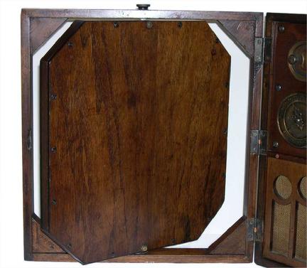
Before winding a new antenna I want to be sure about the direction, pattern, and connection of it. These sticks have notches cut in them on both sides, enough for 18.5 loops of wire top and bottom. I see three contact points on the octagonal box-- two metal posts with button ends that help secure the lid, and a wiper spring on the bottom. An all-in-one drawing based on an AR812, which this radio is supposed to be like, indicates only 14 loops of wire with only two connections. The drawing is of no help. An online search lands me on the website of CFP-Radio, a French radio designer and restorer, and photos of his original assembly. His photos show exactly what is needed.
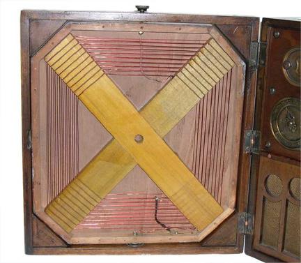
#18 wire was used originally, judging from a remaining fragment, but I have only #22 on hand. Since my new antenna will be hidden inside the lid I decide to go ahead and use the thinner wire. No one but you and I will know about the cheat! There are small eyehooks to anchor wire at each end of the coil. I start at the inside anchor and make a loop, cross to the top for another loop, then to the bottom again, and so on. The notches are so precisely cut that they form the wire into a perfectly consistent spiral.
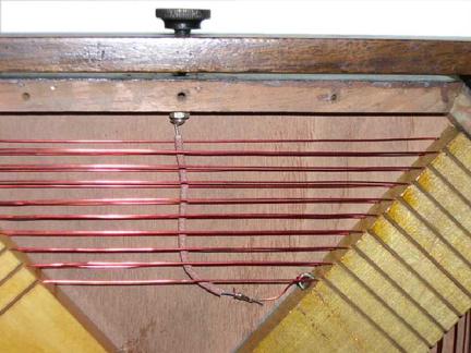
Once all loops are in place I anchor the other end to the remaining eye hook and solder the loop’s ends to the assembly’s top and bottom contact points. Our Frenchman’s photos clearly show a tap at 1.5 loops from the inner end, which is brought out to a wiper contact through the bottom.
|
 |
| Loop connection to upper button screw |
|
|
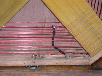 |
| Loop connection to lower button and pivot. |
|
|
 |
| One of two rear antenna mouting clips |
|
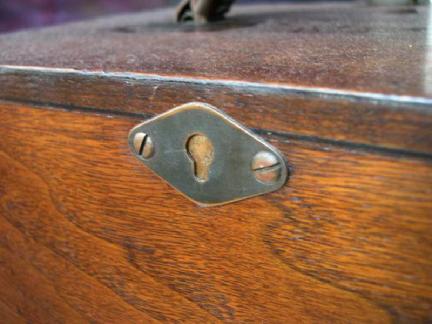
| Why is there a tap on the antenna loop? After some thought, I realize it helps solve a problem. Since this is a “portable” radio, RCA probably figured it would be nice to carry the radio while listening to it. That could be awkward with the lid/antenna opened and swinging around, and not practical with the lid closed, so they designed a way to detach the antenna assembly. It can be removed from the lid by loosening a single thumb screw and then attached to the rear of the radio where there are two clip-like mounts for it. The empty lid frame can then be closed for easy carrying yet the radio can still be clearly heard. (Other Radiola models switch off when the lid is closed. Model 26 has no switch.)
A removable antenna is clever but why a tap on the antenna loop? When the designers came up with their idea for a removable antenna they had to contend with the fact that a loop antenna is part of a carefully tuned circuit. The loop behaves somewhat differently when placed at the front or rear, due in part to its proximity to the radio and in part to connecting wire lengths. To compensate, the rear mounts connect the entire antenna loop length while front mounting uses the tap, effectively shortening the antenna length and changing its tuned characteristics. Cool feature! When mounted on the front, the pivot mount allows you to swing it around to just the right direction for best reception. Also cool.
|
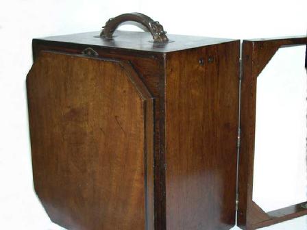 |
| Antenna mounted on radio's back |
|
|
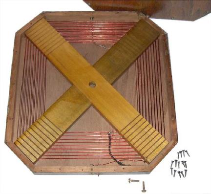
Contact cement secures our wooden cross/loop antenna inside its box. No more rattles and I like the smell of contact cement.
next-->
|
|
|