Repair of an RCA Radiola 26
© 2009, Richard Fairbanks
|
An antenna is of no use unless it is connected to the other radio circuits, naturally. Wires for this purpose are routed through the lid’s frame to its hinges, and from those hinges into the radio. The hinges are a critical link in the wiring and my trusty ohm meter shows they are not working well. They swing easily but the connection through them is horrible.
|
 |
| Hidden wires are soldered to each hinge |
|
|
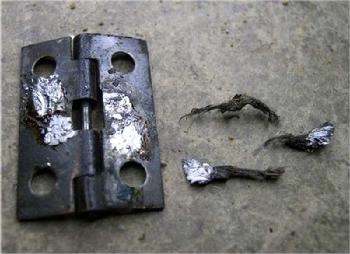
A short length of flexible braid was originally soldered between the two halves to guarantee a perfect electrical connection. Years of flexing have taken their toll and the braids are now in pieces.
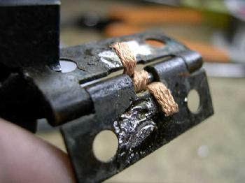
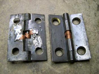
Narrow solder wick turns out to be a perfect replacement.
Finally there is good continuity along the entire antenna loop path, through the case and back. My new antenna should be good to go.
What is next?
|
 |
| Old braid has disintegrated |
|
|
 |
| New copper solder wick fits perfectly |
|
|
 |
| Ready for the next 80 years |
|
|
 |
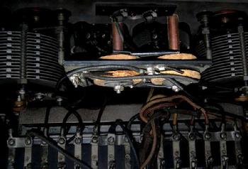
| Main oscillator tuning coils |
|
| Four coils, connected as two pairs, are mounted behind the front panel, centered between the two tuning capacitors. A check of their continuity finds a few ohms across each one. They are probably okay.
I see a few minor repairs to a couple of wires. A short wire has broken off where it was soldered to the outside of the metal catacomb, underneath the terminal block. More on that wire later.
The catacomb has 13 wires that emerge from it, most of which connect to a long terminal block beside it. Old timers refer to these wires as “whiskers” (Catacomb whiskers, get it?). There are 16 positions on the terminal block. Consulting an "all-in-one" circuit drawing, at first I did not realize that different radio models connect the whiskers to different terminal block points! I draw my own hookup chart and regain sanity. Referring to a detailed schematic of the catacomb's circuits, courtesy Mr. Douglas, I measure resistances between each of the 13 whiskers and the catacomb’s tube sockets, just as I did years ago, and once again find no continuity between whisker 11 (B+ line) and the IF tube's plate. The 2nd IF transformer may have a broken primary winding. This is the problem I saw years ago. I continue checking.
|
|
|
One cool trick is to test individual sections by inserting one tube at a time and applying power. (Careful! With only one tube inserted, the filament voltage must be adjusted down.) I find the oscillator section does not oscillate. Resistance checks reveal nothing at all wrong so I look more closely at those oscillator coils I measured earlier. They are essential to the oscillator's functioning. They have continuity but perhaps one of them is partially shorted? To test the theory I unhook the coil/tuning capacitor assembly from the catacomb and clip them to an RF generator and an oscilloscope. By rotating the capacitor I can see the disconnected assembly resonate between 225 kHz up to around 900 kHz. The catacomb’s oscillator should run at or near these same frequencies when connected. With knowledge that the oscillator’s 2nd harmonic (not the fundamental as with most radios) is used for heterodyning, this range makes sense and proves the coils are good. Once again, a finger points into that catacomb box. There must be a problem in there that does not show up with my simple resistance checks. Having run out of excuses it is time to face my fears. I'm going in!
next-->
|
|
|