Repair of an RCA Radiola 26
© 2009, Richard Fairbanks
|
 |
| Frame reassembled |
|
|
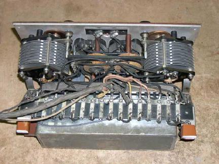
The reassembled catacomb is screwed onto the frame and reconnected to the terminal block, and my radio works! You may notice some brown vinyl tape in this photo. The tape is temporarily holding two new shock absorber pads to the radio’s frame. Remnants of glue are all that remain of the original pads. I’ve fashioned replacements of, of all things, silicon bathroom caulk poured into small raisin snack boxes! The pads have an important function which will become more obvious when we operate the radio later.
|
|
The two tuning capacitors turn smoothly but take strong fingers. Their knobs are small and have a lot of resistance. Maybe a cleaning will free them up?
Each capacitor has its own friction gear reduction drive assembly. I take the first one fully apart only to find there is no practical way to extricate the capacitor rotor from the body, making a thorough cleaning difficult. The best I can do is work a little light oil into the bearing to dissolve some grunge, then blot out as much as possible onto a paper towel. Reassembling the friction gears is much harder than taking them apart was. It is so hard that I decide not to take the other one apart at all. I simply remove a few gear shafts for cleaning/greasing, leaving the gears in position fully meshed. Maybe both assemblies work a little smoother than before or maybe not. They use “friction” gears, after all!
|
|
|
|
|
|
There are three capacitors mounted to the frame, around the catacomb. One of them is a rather large block, a bypass capacitor for B-plus voltage, that has been loose within the radio for quite some time, judging by its battered appearance. Perhaps it broke free during shipment to me from that punk thief years ago. The capacitor is held inside the radio now by only a few strands of its connecting wires, otherwise it might easily fly away like a baby in a train wreck!
I have been thinking it will need to be restuffed with new parts, since capacitors of this vintage are so often unuseable. This one shows only a tiny bit of leakage, on the order of a few microamps, so I decide to leave it alone. I'm not even going to paint it! I fashion new “L” shaped mounting tabs out of solder wick and silver solder. The new tabs slide under existing mounting screws in the frame. The capacitor will be held very securely by these surprisingly sturdy tabs for years to come.
next-->
|
|
|
|
|
|
|