Repair of an RCA Radiola 26
© 2009, Richard Fairbanks
|
|
| With the speaker reinstalled it is time to do final checks, which reveal only that the radio is dead! I cannot believe it. As I am jiggling things and checking connections and mumbling “mint condition” over and over the radio suddenly buzzes with static, and I can tune a station! Then, just as suddenly, it is dead again.
I pull the radio out of the box once more and find that a wire from the terminal block to those oscillator coils has broken. The slightest movement causes it to make or break connection. The fix is made, the radio works, I put the radio back in its box and…nothing!!! Dead again. “Mint condition mint condition mint condition!” Out it comes. Another wire has broken, the A-minus wire to the battery rheostat. Being the shortest wire from the battery cable it probably takes the brunt of movement and stress. I extend the wire a couple of inches and we’re good to go.
|
 |
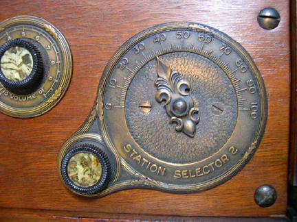
| Dial scales were typically marked 0 to 100 |
|
|
Like many radios of the era, this one's tuning dials are marked with a linear scale of 0-100. Like the original owner probably did so many years ago, I begin to make a chart showing where local stations appear on the Radiola's dials, but I am battling powerful microphonics. The slightest tap on the radio sets off a self sustaining wave of squeals and howls. The volume control has only partial effect on them; some squeals are present even with the volume turned all the way down. It is best to turn the radio off to squelch them and begin again.
|
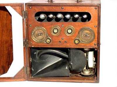
I have new isolation pads for the speaker mounts and on the radio’s frame, and still there are severe microphonics. Audio vibrations from the speaker are passing through the wooden cabinet and into the tubes, which amplify them further. It is feedback just like you'd hear from a public address system. The howls are self-sustaining. The radio’s volume control functions ahead of the 1st AF circuit, which means that any noises introduced into a tube after that point will be uncontrollable. Turning the volume down will not affect them. By lightly tapping each tube I find that the oscillator, detector, and 1st AF tubes are my worst offenders. Tube swapping is required. I want the least sensitive (to microphonics) tubes in the most sensitive positions. Altogether I own eight UV199s to choose from.
These tubes are held into their sockets by a short pin that peeks out of the tube's base. A push and twist motion is required to insert or remove a tube, which is difficult to do through the narrow access provided by the radio's front panel. One of my tubes already has a loose base and it makes a little crunching noise when I twist it into place. I wince and find it’s glass is looser than it was moments ago. I am starting to get nervous. After a few more push/twists, a second glass envelope has loosened up. A few wraps of blue painter’s tape around each glass-base joint stabilizes them for now.
Swapping takes time but eventually I find the best positions for good performance with lowest microphonics. Imagine how much worse microphonics might be without new speaker and frame isolation pads! Once the best lineup is found, my blue tape is removed and a few dots of flexible glue into the seams help secure them. Tubes often get hot enough to melt many glues but these tubes use so little power that they are never more than slightly warm. The choice of glue is not critical as long as it retains some “give” when set. I prefer to use a fast drying clear contact cement from Duco that remains permanently flexible. Cyanoacrylate would set fast but it also becomes very stiff and has been known to crack glass envelopes over time.
|
 |
| All done and ready for the covers |
|
The tuning range measures from approximately 530 kHz (Dials at 100) to 1550 kHz (Dials at 1). A chart of dial settings for some local stations is in the appendix. Contrary to modern expectations, many early radios tune higher frequencies at lower dial numbers. Oh, too bad, Radio Disney at 1560 kHz will be just out of reach!
This radio is designed to use the oscillator’s second harmonic to make the IF frequency. Because the oscillator and RF peaking controls are separate knobs (right and left respectively) it is easy to get double images, where the same station can be appear with two different oscillator settings. Double images also make it easy to determine the radio’s IF frequency. I can tune 530 kHz with the oscillator running at 238 kHz (100 on the scale), and equally well with the oscillator running at 278 kHz (90 on the scale). Some simple math shows our IF stage is peaked at 40 kHz. One of the schematics I’ve been referring to mentions an IF frequency of 42 kHz. This one is definitely peaked at 40 kHz, though, and it cannot be adjusted. I do not think RCA ever gave an official number and component/construction tolerances at the time were loose enough to allow such a variation. Each radio is probably a little different.
|
There is one more thing to do. Remember that short wire between the terminal block and catacomb can? A Rider’s drawing shows it connected to whisker 8, which is one side of the tube filaments where C-plus is connected. Other drawings show whisker 9, the other side of the filaments where B-minus is connected. I cannot imagine why the B-minus point would not be best but I try both to be sure. I cannot detect any difference using a regulated power supply (a battery might be different) and I leave it connected to whisker 9.
This radio’s performance is impressive, all things considered. Sound quality is no worse than many other horn speakers of the day, which is terrible by today’s standards, but there is plenty of gain and enough selectivity to pull in several stations better than many relatively modern radios in my collection. It has a beautiful and graceful look, rather “high tech” for the mid twenties. The Radiola 26 was born the same year my father was. I wish I could restore him as easily.
-c2009
Richard Fairbanks
all rights reserved
|
|
|